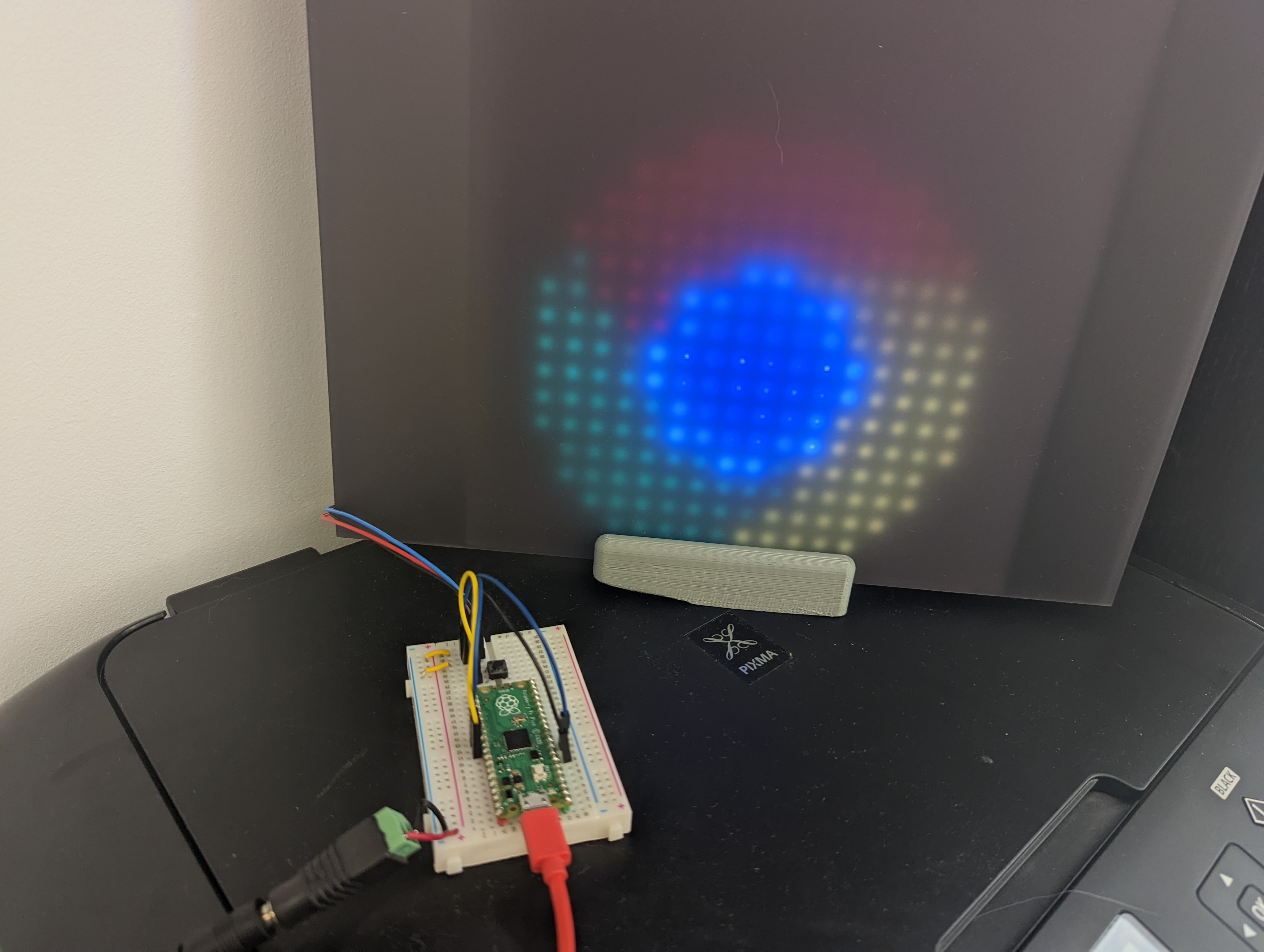
Last year, I got one of those LED grids from AliExpress and I wanted to connect it to my computer, while allowing others to control what is displayed from a web page.
To achieve that, I used a Raspberry Pi Pico connected to my computer to control the LED grid, while controlling the Pico itself via Web Serial and using Firebase Realtime Database to allow others to remotely change what is rendered.
This is a 3-part blog post covering:
- Part 1: Control an LED Grid from Pico using the serial port.
- Part 2: Control the Pico using Web Serial from the computer.
- Part 3: Remotely control the LED Grid from a web page.
Part 1 - Control a LED Grid with the Raspberry Pi Pico
What you will need
- Raspberry Pi Pico.
- LED Grid like this one.
- External 5V / 5A power source.
- Breadboard.
- Breadboard jumper wires.
The LED Grid has 256 LEDs, distributed in 16 columns and 16 rows. Each LED can consume up to 20mA
(milliamps) of power, when set to white. On total, the entire LED Grid can consume up to around 5A,
which is way higher than what can be powered via the USB port powering the Pico, so an
external power supply capable of handling that is needed.
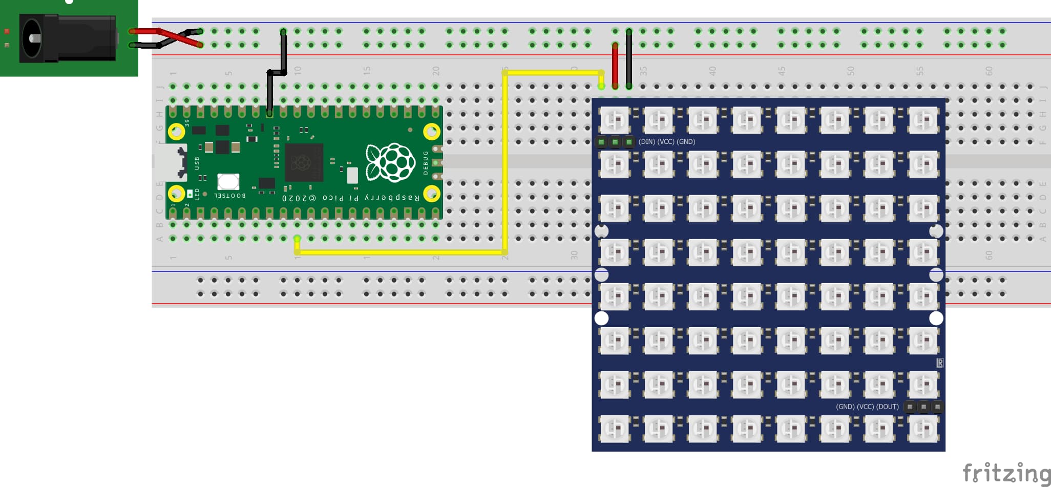
To power the LED grid, the external power supply is connected to the power rails on the breadboard, and the rails are connected VCC and GND on the LED grid.
GPIO7 (Pin 10) on the Pico is used to to control the LED grid, so Pin 10 on the Pico is connected to DIN on the LED grid, and the circuit is closed by connecting one of the GND pins on the Pico to the ground power rail.
This diagram shows how things should look like with everything connected:

Note: It is possible to power the Pico with the external power source by connecting the positive power rail to VSYS (Pin 39). In this project, since the Pico will be connected to the USB for the serial communication, it can draw power from the USB port and doesn't need to be connected to VSYS.
Getting started with LED strips
There are different models of LED strips out there. Some, like the ones based on WS2801 can be controlled via the SPI bus - this make them ideal to be controlled from computers like the Raspberry Pis.
However, the LED controllers used on this LED grid is the WS2812B. Instead of
using a higher level protocol, like SPI or I2C, sending data to those controllers is achieved
by setting pins to HIGH and LOW with specific timings, with a technique called
bit banging.
Bit banging and the Pico PIO
Implementing bit banging usually requires very careful programming, due to the interaction of the specific timings required by the protocol, the CPU clock cycle and other parts of the code that also use the CPU clock cycle.
The Pico adds a feature called Programmable Input/Output (PIO). It implements a state machine connected to a FIFO queue that exchange data with the main program have access to the board's GPIO, making the code for the protocol and other parts of the code independent, in terms of clock cycles. An explanation of the Raspberry Pi Pico PIO is outside the scope of this article, and has already been covered by a number of online resources, like this blog post.
The Raspberry Pi Pico Examples repository implements the protocol needed on the ws2812 example, with timings adjusted to work with the ws2812b:
.program ws2812b
.side_set 1

.define public T1 3
.define public T2 4
.define public T3 3

...
The Raspberry Pi Pico SDK CMake file will take the .pio program and generate the related code,
introducing the ws2812b_program_init() method to the application, which allows initialising the
state machine with the pio port, the pin it controls and the clock. Data is sent to the LED strip
by calling pio_sm_put_blocking().
class LedStrip {
public:
    PIO pio;
    uint32_t *buffer;
    int pin_tx;
    int length;
    int sm = 0;
    LedStrip(PIO pio, int pin_tx, uint32_t buffer[], int length):
            pio(pio), pin_tx(pin_tx), buffer(buffer), length(length) {
        uint offset = pio_add_program(pio, &ws2812_program);
        ws2812_program_init(pio, sm, offset, pin_tx, 800000, false);
    }

    void clear() {
        for (int i = 0; i < length; i++) {
            buffer[i] = 0;
        }
    }

    void update() {
        for (int i = 0; i < length; i++) {
            pio_sm_put_blocking(pio, 0, buffer[i] << 8u);
        }
    }
};
Those details are encapsulated in the LedStrip class. Besides storing information needed to control the PIO the class also stores an array buffer where each index represents the pixels on the LED strip.
From LED strip to LED grid
You may noticed the reference an LED strip instead of a grid a few times in this arcticle so far. This is due to, in reality, the LED grid being a LED strip where the way rows and columns are mapped can be unintuitive.
Instead of following a left-right pattern across the whole grid, the LED strip snakes around the board, so that columns on even rows are refenced from left to right and columns on odd rows are referenced from right to left - while it would be expected for (1, 0) to reference the first LED of the second line, it actually points to the last one.
class LedGrid: public LedStrip {
public:
    int width;
    int height;
    LedGrid(PIO pio, int pin_tx, uint32_t buffer[], int width, int height):
            LedStrip(pio, pin_tx, buffer, width * height), width(width), height(height) {
    }

    void set_pixel(int x, int y, uint32_t color) {
        if (x % 2 == 0) {
            buffer[x * height + y] = color;
        }  else {
            buffer[(x + 1) * height - y - 1] = color;
        }
    }
};
The LedStrip implementation can be extended into a LedGrid and implement a set_pixel() method
that caters for that difference.
Testing the LED Grid
Before moving forward with enabling the serial port, it is possible to thes the LED grid by hard coding an image into the code:
const int PANEL_WIDTH = 16;
const int PANEL_HEIGHT = 16;
const int PIN_TX = 7; // The GPIO port controlling the LED grid.
const int NUM_LEDS = PANEL_WIDTH * PANEL_HEIGHT;

// The pixels for the Chrome logo.
const uint32_t CHROME_LOGO[256] {
        0x000000, 0x000000, 0x000000, 0x000000, 0x000000, 0x001400, 0x001400, 0x001400, 0x001400,
        0x001400, 0x001400, 0x000000, 0x000000, 0x000000, 0x000000, 0x000000, 0x000000, 0x000000,
        0x000000, 0x011500, 0x001400, 0x001400, 0x001400, 0x001400, 0x001400, 0x001400, 0x001400,
        0x001400, 0x011500, 0x000000, 0x000000, 0x000000, 0x000000, 0x000000, 0x001100, 0x001300,
        0x001400, 0x001400, 0x001400, 0x001400, 0x001400, 0x001400, 0x001400, 0x001400, 0x001400,
        0x001400, 0x000000, 0x000000, 0x000000, 0x000F00, 0x001000, 0x001200, 0x001400, 0x001400,
        0x001400, 0x001400, 0x001400, 0x001400, 0x001400, 0x001400, 0x001400, 0x001400, 0x011500,
        0x000000, 0x000000, 0x080001, 0x000F00, 0x001100, 0x001300, 0x001400, 0x001400, 0x1B1B1B,
        0x1B1B1B, 0x081500, 0x081700, 0x091800, 0x0A1900, 0x0B1B00, 0x0C1D00, 0x000000, 0x080001,
        0x080001, 0x000B00, 0x001000, 0x001200, 0x1B1B1B, 0x0F091B, 0x05001C, 0x05001C, 0x0F091B,
        0x1B1B1B, 0x0D1E00, 0x0E1E00, 0x0E1E00, 0x0E1F00, 0x0F1F00, 0x080001, 0x080001, 0x080001,
        0x000C00, 0x001100, 0x0F091B, 0x05001C, 0x05001C, 0x05001C, 0x05001C, 0x0F091B, 0x0F1F00,
        0x0F1F00, 0x101F00, 0x101F00, 0x111F00, 0x080001, 0x080001, 0x080001, 0x030200, 0x1B1B1B,
        0x05001C, 0x05001C, 0x05001C, 0x05001C, 0x05001C, 0x05001C, 0x1B1B1B, 0x111F00, 0x111F00,
        0x111F00, 0x111F00, 0x080001, 0x080001, 0x080001, 0x080001, 0x1B1B1B, 0x05001C, 0x05001C,
        0x05001C, 0x05001C, 0x05001C, 0x05001C, 0x1B1B1B, 0x111F00, 0x111F00, 0x111F00, 0x111F00,
        0x080001, 0x080001, 0x080001, 0x080001, 0x080001, 0x0F091B, 0x05001C, 0x05001C, 0x05001C,
        0x05001C, 0x0F091B, 0x111F00, 0x111F00, 0x111F00, 0x111F00, 0x111F00, 0x080001, 0x080001,
        0x080001, 0x080001, 0x080001, 0x1B1B1B, 0x0F091B, 0x05001C, 0x05001C, 0x0F091B, 0x1B1B1B,
        0x111F00, 0x111F00, 0x111F00, 0x111F00, 0x111F00, 0x000000, 0x080001, 0x080001, 0x080001,
        0x080001, 0x080001, 0x080001, 0x1B1B1B, 0x1B1B1B, 0x050001, 0x111F00, 0x111F00, 0x111F00,
        0x111F00, 0x111F00, 0x000000, 0x000000, 0x070001, 0x080001, 0x080001, 0x080001, 0x080001,
        0x080001, 0x080001, 0x070001, 0x040001, 0x111F00, 0x111F00, 0x111F00, 0x111F00, 0x101E00,
        0x000000, 0x000000, 0x000000, 0x080001, 0x080001, 0x080001, 0x080001, 0x080001, 0x080001,
        0x050001, 0x111F00, 0x111F00, 0x111F00, 0x111F00, 0x111F00, 0x000000, 0x000000, 0x000000,
        0x000000, 0x000000, 0x070001, 0x080001, 0x080001, 0x080001, 0x070001, 0x111F00, 0x111F00,
        0x111F00, 0x111F00, 0x0F1B00, 0x000000, 0x000000, 0x000000, 0x000000, 0x000000, 0x000000,
        0x000000, 0x000000, 0x070001, 0x070001, 0x060001, 0x111F00, 0x111F00, 0x0E1B00, 0x000000,
        0x000000, 0x000000, 0x000000, 0x000000,
};

int main() {
    stdio_init_all();

    // Buffer for holding the values for the LED strip.
    uint32_t buffer[NUM_LEDS];
    auto ledGrid = LedGrid(pio0, PIN_TX, buffer, PANEL_WIDTH, PANEL_HEIGHT);
    ledGrid.clear();
    for (int x = 0; x < 16; x++) {
        for (int y = 0; y < 16; y++) {
            uint32_t color = CHROME_LOGO[y * PANEL_WIDTH + x];
            ledGrid.set_pixel(x, y, color);
        }
    }
    ledGrid.update();
}
Now, with everything connected, build the project and copy the uf2 file to the Pico. Once it
reboots, you shoudl see the Chrome logo rendered.

Enable UART and read data from the USB
The Pi Pico has 2 UART ports and, by default, those are enabled on the GPI pins. To enable UART over the USB port, the following lines need to be added toCMakeLists.txt:
# enable usb output, disable uart output
pico_enable_stdio_usb(pico_ledstrip 1)
pico_enable_stdio_uart(pico_ledstrip 0)
The final step to setup the UART is to ensure the program is calling stdio_init_all() - this
makes the standard I/O functions, like printf(), send data to the serial port instead.
stdio_init_all();

// Buffer for reading values from stdinput.
uint8_t read_buffer[NUM_LEDS * 3];

// Buffer for holding the values for the LED strip.
uint32_t buffer[NUM_LEDS];

auto ledGrid = LedGrid(pio0, PIN_TX, buffer, PANEL_WIDTH, PANEL_HEIGHT);
while (true) {
    printf("Waiting for data\n");
    fread(read_buffer, 1, NUM_LEDS * 3, stdin);
    for (int x = 0; x < 16; x++) {
        for (int y = 0; y < 16; y++) {
            int start_index = (y * PANEL_WIDTH + x) * 3;
            uint8_t red = read_buffer[start_index];
            uint8_t green = read_buffer[start_index + 1];
            uint8_t blue = read_buffer[start_index + 2];
            ledGrid.set_pixel(x, y, urgb_u32(red, green, blue));
        }
    }
    ledGrid.update();
    printf("Received data\n");
}
A new buffer, read_buffer, is introduced to read data from the serial port. Then, LedGrid is initialized with the PIO port used, the pin connected to the LED grid data line, the buffer, and the width and height for the LED strip.
It then enters an infinite loop where the program blocks on the fread() call until read_buffer
is full, then sets the colours to the LED strip via set_pixel(). Finally, it updates the display by calling update().
Next Step
You now have an application that will run on the Raspberry Pi Pico and control the LED Grid. You can download a pre-build uf2 and build your own, then copy the uf2 file to the Pico. Then, with the pico connected
to your computer, navigate to https://ledmoji.bandarra.me/ and click Connect. You should be able to select your Pico and control the connected LED grid.
On the next part, you will learn how to connect to the Pico using WebSerial! Stay tuned! And, in the meantime, check out the full code for the project on Github.
